A transformer is a static electrical device that transfers electrical energy from one circuit to another through electromagnetic induction, without any physical connection. Since, a transformer works bases on electromagnetic induction, it only works on an AC supply and can step up or step down voltage levels without changing its frequency. The transformer consists of primary and secondary windings wound around a common magnetic core, which helps in efficient energy transfer while maintaining electrical isolation between the circuits. Now, we shall derive with explanation on every step of the EMF equation of a transformer, here in this article.
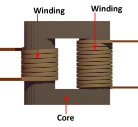
A very basic transformer model has two coils or windings, wound around a common iron core. However, more than two-winding transformers exist, but in the basic design, there are mainly two windings. One winding is connected to the input alternating voltage source, while the other is connected to the output load.
Now, to understand the EMF equation of a transformer. For that, we shall first consider an ideal transformer. Obviously, the ideal transformer is an imaginary transformer that has no core losses, no copper losses, and perfect magnetic coupling.
- No core losses means hysteresis loss plus eddy current loss is zero.
- No copper losses imply that the windings have zero resistance.
- Perfect magnetic coupling means there is no leakage flux, i.e. all flux links both windings.
EMF Equation of a Transformer
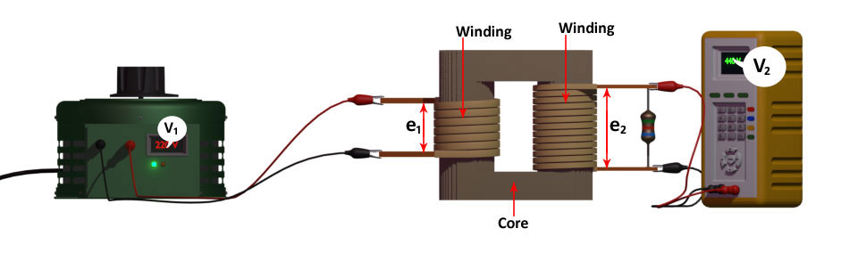
Suppose there is an ideal transformer with an open secondary winding. In addition, we apply an alternating voltage to the primary winding. Say, the voltage is \( v_{1} \).
\[ v_1 = v_{1m} \sin2\pi f t \;\;Where,\;v_{1m}\;is\;the\;peak\;voltage. \]
Under this condition, the primary winding draws a small current (magnetizing current) to establish an equal and opposite EMF across the winding. Obviously, this is self-induced EMF in the primary. That means, self-induced EMF \( e_{1} \) is, at any instant, equal to and in opposition to \( v_{1} \). The primary draws only magnetizing current to establish the counter EMF. Since the winding is purely inductive, the magnetizing current \( I_{\mu} \) lags behind the applied voltage \( v_{1} \) by 90°. Subsequently, this alternating current \( I_{\mu} \) produces an alternating flux \( \phi \). This flux is proportional to the current and hence it is in phase with the current.
\[ \phi = \phi_{m} \sin2\pi f t \;\;Where,\;\phi_{m}\;is\;the\;peak\;flux. \]
Without a doubt, this changing flux links with both windings. Hence, the secondary winding produces an induced EMF \( e_{2} \). That is why we call it mutually induced EMF. Obviously, the EMF is in phase opposition with \( v_{1} \), and its magnitude is proportional to the rate of change of flux and the number of secondary turns.
\[ e_2 = -N_2 \frac{d\phi}{dt} \;\;volt \]
We can similarly write the self induced primary emf as\[ e_1 = -N_1 \frac{d\phi}{dt} \;\;volt \]
Voltage Ratio
Hence, the self induced primary emf and mutually induced secondary emf are\[ e_1 = -N_1 \frac{d\phi}{dt} = -N_1 \frac{d(\phi_{m} \sin2\pi f t)}{dt} = -N_1 \phi_m \cos 2\pi f t \times 2\pi f \]\[ e_2 = -N_2 \frac{d\phi}{dt} = -N_2 \frac{d(\phi_{m} \sin2\pi f t)}{dt} = -N_2 \phi_m \cos 2\pi f t \times 2\pi f \]
We can express these equations as vectors i.e. instantaneous values. If \( E_{1} \) and \( E_{2} \) are the RMS values of \( e_{1} \) and \( e_{2} \). Then, to obtain the RMS value of EMF \( e_1 \) and \( e_2 \), divide their maximum value by \( \sqrt{2} \) \[ E_1 = \frac{2\pi}{\sqrt{2}} f N_1 \phi_m = 4.44 f N_1 \phi_m \;\;\&\;\; E_2 = \frac{2\pi}{\sqrt{2}} f N_2 \phi_m = 4.44 f N_2 \phi_m \] Although, the cosine term has no significance except to derive the instantaneous values.
In an ideal transformer, \[ V_1 = E_1 \]\[ V_2 = E_2 \] Where, \( V_1 \) is the primary source terminal voltage and \( V_2 \) is the secondary terminal voltage.
\[ \frac{E_2}{E_1} = \frac{N_2}{N_1} = K \] Since this is the ratio of primary and secondary voltage, we call this constant the voltage transformation ratio.
Common Form of the EMF Equation of a Transformer
Therefore, we can represent the common form of the emf equation of a transformer as follows, \[ E = 4.44 f N \phi_m\]Where, E is the emf across any of the windings and N is the number of turns of that winding.