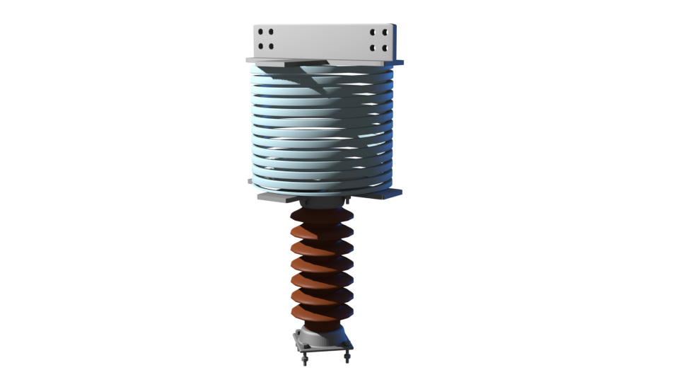
In substations, we always see some reactors connected in series with the capacitor bank. First, a circuit breaker along with an isolator connects the capacitor bank to the system bay. After the capacitor bank, a reactor comes in series with each branch of every phase of the capacitor.
Understanding the Inrush Current
Now, the question arises: why do we use reactors with the capacitor bank?
If the capacitor does not have any charge initially, there will be no voltage across it. When we switch on the capacitor bank using the circuit breaker, i.e., when the circuit breaker contacts close, the system voltage appears across the capacitor. The voltage appears across the capacitor instantly, and this rapid change in voltage causes a huge current to flow through the capacitor.

Mathematical Explanation of Inrush Current
We can explain it like this: whenever we apply a voltage across a capacitor, the capacitor starts to accumulate charge, denoted by Q. The quantity of charge stored is directly proportional to the applied voltage, following the equation:\[Q = C \times V\]Where C is the capacitance and V is the voltage. This means the greater the voltage, the more charge the capacitor holds.
Expression of Inrush Current
Now, the voltage across the capacitor changes rapidly because it is applied suddenly. So, there will be a high rate of change of voltage with respect to time. Differentiating the equation \(Q = C \times VQ\), we get:
\[ \frac{dQ}{dt} = C \times \frac{dV}{dt}\]
This indicates that the current \( I = \frac{dQ}{dt}\) is directly proportional to the rate of change of voltage \(\frac{dV}{dt}\), assuming C is constant.
Here, \( \frac{dV}{dt}\) is very high, so \( \frac{dQ}{dt}\) is also very high. We know that \(\frac{dQ}{dt}\) is the rate of change of charge with respect to time, which is nothing but the current. So, during switching on the capacitor, a huge current flows through it. This current can reach 10 to 100 times the rated current of the capacitor bank. We refer to this large surge of current as the inrush current. But this high current, or inrush current, does not last long. It becomes damped immediately within a few milliseconds.
However, due to the presence of capacitance of that capacitor and the other capacitors connected to the system, and due to the system inductance, a natural resonance circuit may be created. Due to this resonance, the inrush current starts oscillating.
The natural frequency of this oscillation depends on the inductance and capacitance values of the system and can be very high, ranging from 2 kHz to 10 kHz. The inherent reactance and resistance of the system quickly damp out this current.
System Impact of Inrush Current
During capacitor switching, it is obvious that such a large inrush current can cause a sudden voltage drop in the system – known as a voltage dip.
One problem due to this voltage dip is the possibility of unnecessary under-voltage tripping in the system. Secondly, this large inrush current may cause permanent damage to system equipment. In fact, the capacitor bank itself may sustain permanent damage as a direct consequence of this current. Also, the excessive current may blow the fuses of the capacitor elements.
How Reactors Help
Therefore, to limit the inrush current during capacitor bank switching, a suitable arrangement must be implemented. This is where the reactors come into the picture. Generally, we connect an inductor (reactor) in series with each branch of each phase of the capacitor bank. The reactance of an inductor or reactor is directly proportional to the frequency of the current passing through it. Here, the frequency of the inrush current is very high, so the inductor offers a high reactance to that inrush current. Therefore, it limits the current inrush.
Standard Reactance Range of Reactors
Generally, we choose the reactance of the reactor for this purpose between 0.1% to 0.5% of the capacitor’s reactance. You might say there is already inherent inductance in the system, so why do we need an extra inductor (or reactor) in series with the capacitor bank?
Yes, the system always has inherent inductance. Because of the inherent inductance and capacitance, a resonance circuit can form during capacitor switching. But current-limiting reactors come into the circuit only when we switch on a capacitor bank. Otherwise, they remain out of the circuit and do not disturb the system performance. The current-limiting reactors do not cause any significant voltage drops, since their reactance is minimal compared to the total system reactance.
Calculating Reactance of a Reactor: An Example
Let us now calculate the reactance of the reactor. As per standard practice, the reactance of the current-limiting inductor is selected as 0.1% to 0.5% of the reactance of the capacitor bank. For example, assume we have taken 0.2% of the total reactance of a capacitor bank as the rating of the series reactor or inductor. This inductor is usually an air-core inductor, because air-core inductors perform most efficiently at high frequencies. Since, the inrush current is a high-frequency signal, it is preferable to use air-core inductors to limit that current.
Now suppose Q = 10 MVAR is the capacity of the capacitor. It is installed across a 33kV system. From this, we can calculate the reactance of the capacitor. We know the reactive power per phase is
Capacitor bank rating: \( Q = 10 \, \text{MVAR} \)
System voltage: \( 33 \, \text{kV} \)
Target reactor reactance: \( 0.2\% \) of \( X_C \)
- 1. Reactive Power Per Phase: \[ \frac{Q}{3} = \frac{10 \times 10^6}{3} = 3.33 \times 10^6 \, \text{VAR} \]
- 2. Phase Voltage: \[ V_{\text{phase}} = \frac{33}{\sqrt{3}} = 19.04 \, \text{kV} \]
- 3. Capacitor Reactance per Phase \( X_C \): \[ Q_{\text{per phase}}=\frac{Q}{3} = \frac{V_{\text{phase}}^2}{X_C} \] \[ X_C = \frac{(19.04 \times 10^3)^2}{3.33 \times 10^6} \] \[ X_C = \frac{362521600}{3330000} = 108.9 \, \Omega \]
- Using this and formula \( \frac{1}{2\pi f C} \), and after calculation, we get
- 4. Capacitance \( C \): \[ X_C = \frac{1}{2\pi f C} \] \[ \Rightarrow C = \frac{1}{2\pi \cdot 50 \cdot 108.9} \] \[ \Rightarrow C \approx 29.21 \, \mu\text{F} \]
- 5. Required Reactor Reactance \((0.2\%\, of \, X_C )\): \[ X_L = 0.2\% \times 108.9 = \frac{0.2}{100} \times 108.9 = 0.218 \, \Omega \]
That is the required reactance of the series reactor.


