An LCR meter is an advanced measuring instrument. We use it to measure the inductance (L), capacitance (C), and resistance (R) of a circuit. It helps determine the precise values of capacitances, inductances and resistances. These are the three basic parameters of an electrical or electronics circuit. It can measure the three circuit parameters: inductance (L), capacitance (C), and resistance (R). Therefore, the name comes as LCR meter. Some advanced LCR meters also measure Q factor (Quality Factor), D factor (Dissipation Factor), impedance (Z), and phase angle (θ)
Working Principle of an LCR Meter
The LCR meter applies a small AC sinusoidal signal to the component under measurement. Then it measures the voltage across that component and the current flowing through it due to the applied AC signal. By simply dividing the measured voltage by the current, it can calculate the impedance of the component. For that it follows the basic V/I relationship as per Ohm’s law. \[Z = \frac{V}{I}\]
However, this basic impedance value does not indicate whether the component is purely resistive, inductive, or capacitive. Therefore, the LCR meter must determine the nature of the impedance — whether it represents resistance, inductance, or capacitance. To distinguish between these parameters, the LCR meter measures the phase angle between the voltage and current waveforms. It checks whether the current leads or lags the voltage, and based on this information, it identifies whether the component is capacitive, inductive, or purely resistive.
Since, the instrument knows the frequency of the applied AC signal, it can accurately analyze the timing of the voltage and current waveforms. It detects the instant when each waveform reaches its peak (maximum value) and calculates the time gap between these two peaks. From this time difference, the instrument determines the phase angle, which ultimately helps in identifying the nature of the impedance.
Principle of Inductance Capacitance, Resistance Measurement
If the phase angle is 0, it means the measured voltage and current reach their peak at the same instant. In such a case, the impedance is purely resistive, and the measured component is a pure resistor.
If the current lags the voltage by 90 degrees, meaning the current peak occurs half a cycle after the voltage peak, the component is a pure inductor. Conversely, if the current leads the voltage by 90 degrees, meaning the current peak occurs half a cycle before the voltage peak, the component is a pure capacitor.
These are the ideal cases. In practical situations, if the phase angle between voltage and current is close to 0 degrees, we consider the component as resistive. If the phase angle is positive and close to + 90 degrees, it is inductive; and if the phase angle is negative and close to – 90 degrees, it is capacitive. From the measured impedance and phase angle, the LCR meter can also calculate the inductance or capacitance.
Inductance Capacitance Measurement Equations
The LCR meter measures the inductive reactance of a component. Using this value, it can easily calculate the inductance (in henries) using the formula \(X_L= 2\pi f L, \) where \(X_L\) is the inductive reactance and f is the frequency. Similarly, it can calculate the capacitance from the measured capacitive reactance \(X_C\) using the appropriate formula \(X_C = \frac{1}{2\pi f C}\).
The instrument injects high frequency ac signal for inductance measurement. Because at high frequency the capacitive reactance of the circuit becomes very negligible. Hence it minimize the influence of capacitance on inductance measurement. In the same way, when we measure a capacitance value we keep the feeding frequency as low as possible. Because, at low frequency, the inductor behaves as short-circuit hence, it minimize the influence of inductance on the capacitance measurement.
In short, we can say, an LCR meter operates by applying a low-magnitude AC signal to the component under test. It measures the voltage across and the current through the component, calculates the impedance, and then determines the inductance (L), capacitance (C), or resistance (R) based on the frequency and the phase relationship between the measured voltage and current.
Measuring Mode of LCR Meters
An LCR meter offers two measurement modes: series and parallel. In series mode, we assume all resistance, capacitance, and inductance are in series. Since, it is more suitable for measuring inductance. In parallel mode, the meter treats resistance as being in parallel with the inductance or capacitance. Because, it is suitable for the capacitance measurement. The choice of mode depends on the expected behavior of the component and the user setting.
Leads Connection of LCR Meters
Portable handheld LCR meters usually use a two-wire connection – simple for basic measurements. However, modern bench-top models often support four-wire Kelvin connections for higher precision: two terminals inject the signal and measure current, and two separate terminals sense the voltage. In handheld meters with test sockets, we can insert the component directly. We can also use alligator or Kelvin clips to connect the leads of the components.
Minimize the Effect of Leads
Before measurement, some meters offer a self-correction calibration (open and short) to eliminate lead-induced inductance and capacitance. Open-circuit calibration eliminates the capacitance of the leads, and a short-circuit calibration corrects for the inductance of the leads, resulting in more accurate, precision readings.
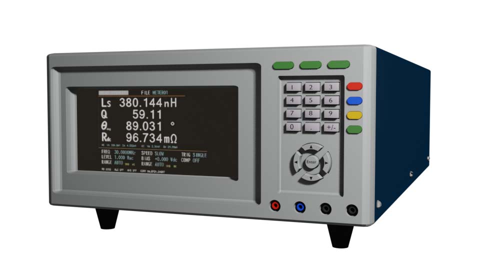
Once set up, the LCR meter displays the measured values of inductance in hernias or millihenries, capacitance in farads or microfarads, and resistance in ohms, megaohms, or milliohms. Advanced meters also provide additional parameters such as Q‑factor, D‑factor, impedance, and phase angle, offering deeper insight into the component’s AC performance.