Why was the gapless ZnO lightning arrester developed over the valve-type lightning arrester?
In a valve-type lightning arrester, we connect spark gaps in series with non-linear resistors. This is necessary because silicon carbide (SiC) has a relatively low non-linearity coefficient (α ≈ 5–7). As a result, the knee point in the V–I characteristic of an SiC resistor is not sharp enough, leading to the possibility of significant leakage current even under normal operating conditions when no surge is present.
Requirement of Spark Gap
To limit this unwanted leakage current, engineers introduced a spark gap mechanism. Hence, under normal conditions, the spark gaps isolate the resistors from the system voltage. During a surge, the high voltage causes the spark gaps to arc, allowing the surge voltage to appear to the SiC resistors. Hence, SiC resistors become conductive and allow the current to flow to the ground.
How to omit Spark Gap
We can overcome this limitation of high leakage current if we use non-linear resistors made from a material with a much higher non-linearity coefficient. In that case, the V–I characteristic exhibits a very sharp knee point. This results in negligible leakage current under normal conditions. Even when we apply the system voltage directly to the resistors. However, once the voltage exceeds the threshold during a surge, the current increases sharply.
Zinc Oxide (ZnO) is such a material, with a non-linearity coefficient of α ≈ 30–50. The non-linearity coefficient essentially indicates how rapidly the current increases with voltage at knee point. A higher α means greater non-linearity. A low α (as in SiC) results in a gradual increase in current, while a high α (as in ZnO) causes the arrester to become highly conductive almost instantly, effectively clamping the voltage.
Because of these advantages, ZnO arresters do not require series spark gaps, making them gapless lightning arresters. For this reason, ZnO has become the preferred material in modern lightning arrester design.
Physics behind the Working of ZnO Blocks
The main component of a gapless ZnO lightning arrester is its column of ZnO blocks. All other parts of the arrester serve as auxiliary components. The base material of ZnO blocks typically consists of 94 to 96% by weight of Zinc Oxide (ZnO), and 4 to 6% by weight of additives such as Bismuth Oxide (Bi₂O₃), Cobalt Oxide (CoO), and Manganese Oxide (MnO₂). After the formation of final blocks, the microstructure contains a large number of fine ZnO grains, with the additives positioned at the grain boundaries.

ZnO is an n-type semiconductor, whereas additives like Cobalt Oxide and Manganese Oxide are p-type materials. This results in the formation of thin p-type layers between the n-type ZnO grains. Free electrons from the ZnO grains migrate into these p-type boundary layers, creating depletion layers at the grain boundaries. Collectively, these depletion layers impede current flow through the blocks in both directions under normal operating conditions.
During a surge event, when the voltage exceeds a certain threshold limit, these depletion layers break down, allowing current to flow freely through the ZnO blocks. Once the surge subsides and the voltage drops below the threshold, the depletion layers reform, restoring the high-resistance state and preventing further current flow.
Construction of Gapless ZnO Lightning Arrester
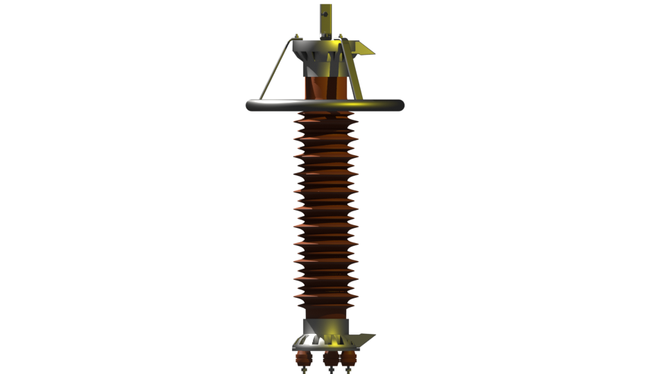
The image illustrates the internal arrangement and key components of a gapless ZnO lightning arrester. The main components of a gapless metal oxide lightning arrester are

The terminal for external connection is located at the top of the arrester. It is directly welded to the upper electrode assembly. The electrodes of the arresters are made of either aluminum or galvanized steel. This terminal provides a point of electrical connection of the LA to the high-voltage system or line.
Spring is positioned directly above the ZnO blocks. This spring remains compressed between the upper electrode and the top ZnO block. So, it maintains consistent mechanical pressure on the ZnO discs. This arrangement ensures proper electrical contact and stability under thermal cycling or vibration.
Sealing Cover is present at both the top and bottom ends. It protects internal components from moisture, dust, and contaminants. Thereby, it maintains internal air-tightness.
Sealing Ring provides a tight seal between the sealing cover and the insulator. It prevents leakage and ensures hermetic sealing.
Zinc Oxide (ZnO) Blocks are the core protective element of the arrester. Each block consists of sintered ceramic discs made of ~94–96% ZnO and 4–6% additives (Bi₂O₃, CoO, MnO₂). The column of ZnO disc exhibits nonlinear voltage-current characteristics, which means high resistance at normal conditions and low resistance during surges.
Porcelain Insulator acts as the outer housing of the arrester. Instead of a porcelain insulator, polymer insulation housing is also used nowadays. The housing mainly offers mechanical strength, electrical insulation, and environmental protection to the ZnO blocks. Its ribbed design increases creepage distance to prevent flashovers.
One venting duck is attached top and bottom covers. Here, cover means electrode assembly. Each of the venting ducts provides a pressure release path in case of overpressure due to internal fault or surge damage. It protects against explosions by allowing controlled venting of gases.
Each venting duct is externally covered with one indicating plate. It indicates internal condition or fault status. Mechanical displacement of the indicating plate may be linked to internal pressure relief through the venting duct when a failure occurs inside.