The High Impedance Bus Differential Protection is a very interesting subject to study. A busbar is a critical component in a power substation. It ensures the proper connection of all incoming and outgoing feeders to a single voltage level system. Obviously, if a fault occurs on the bus itself and does not promptly clear, it may cause permanent damage to the bus system. Moreover, if it damages the bus, a large portion of the substation will experience a blackout. This is because a bus connects many feeders. Therefore, due to its importance, a busbar system requires highly reliable protection schemes to detect and isolate faults promptly.
The high-impedance differential relay scheme is one popular method we use for busbar protection. This article explores the working principles, advantages, design considerations, and practical implementation of a high-impedance bus differential protection system. The primary objectives of a busbar protection scheme are:
Fast fault detection and isolation are essential to prevent damage to the busbar system.
The protection scheme must discriminate between internal and external faults to maintain system stability. This means that a bus differential protection system should actuate the associated circuit breaker tripping only for faults occurring within the bus system. Any fault in the feeders connected to the bus must not actuate the tripping of the circuit breaker. In other words, the busbar differential relay must not operate to any external fault.
Working Principle of High Impedance Bus Differential Protection
A high impedance differential protection scheme operates by detecting the difference in currents flowing into and out of the protected zone. A high impedance differential relay operates when the voltage across its circuit exceeds a threshold value.
Let us discuss the contradiction: the high impedance differential protection scheme functions based on the differential current flowing through the relay, but the high impedance relay itself is a voltage-operated relay.
Current Transformer Connections
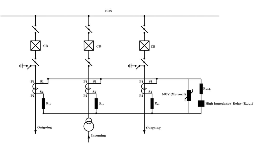
Here, we keep the protection core of the current transformer for each connected feeder to the bus in a parallel configuration. The polarity of each current transformer must be the same. Normally, we orient the P1 terminal of all current transformers towards the bus bar. Then we connect the secondary S1 terminal of all CTs. Also, we connect the other terminal of each core. Lastly, we connect these two common connections (S1 and S2, for example) across a high-impedance relay.
Balanced Condition – No Operation
Since the polarity of all connected CTs is the same, the CT secondary currents cancel each other out in the common circuit of the relay. Therefore, the sum of the CT secondary currents is practically nearly zero, resulting in minimal voltage across the relay. The relay does not operate.
Response to External Faults
The same applies to an external fault. If a fault occurs in one of the feeders connected to the bus, the fault current passes through the feeder CT. Obviously, the source feeder ultimately has to supply the fault current. Therefore, the incoming feeder current of the bus adds this fault current. As both the outgoing and incoming currents increase by the same amount, no resultant current flows through the differential relay, and it does not operate.
Response to Internal Faults
During an internal fault, outgoing feeders do not have to share the fault current fed from the source. As a result, the fault current flows within the protected bus, creating an unbalanced condition. Consequently, the voltage across the relay circuit exceeds the set threshold, causing the relay to trip all the feeders connected to the bus and isolate the faulted bus.
High Impedance Bus Differential Protection Scheme
CT Secondary Connections and Protective Elements
As we have already mentioned, we connect all S1 terminals at a common point. Also, we connect all the other terminals, such as S2 terminals (for example), to another common point. Then we place a stabilizing resistor in series with the relay to limit the impact of CT saturation and ensure stability during external faults. After that, we connect the relay with the stabilizing resistor in series across the common points of the CT secondaries. Additionally, we connect a metrosil (a nonlinear resistor) in parallel to protect the relay from excessive transient voltages, preventing damage and ensuring reliable operation.
Example of a High Impedance Bus Differential Protection Scheme
An example of a high impedance bus differential protection scheme for a 132kV single bus system. Suppose there are two outgoing feeders with a CT ratio of 800/1A and a knee voltage of 800V. Additionally, there is one incoming feeder with the same CT ratio of 800/1A and the same knee voltage of 800V. We arrange the polarities in such a way that the incoming current is additive and all outgoing currents are subtractive, ensuring differential protection. To achieve this, we generally follow the convention of keeping P1 towards the bus side.
Relay Setting in Voltage
We set the High impedance differential relay in voltage. The setting for the relay needs to be low enough for internal faults while preventing unwanted tripping for external faults. The voltage above which the relay acts to trip. Calculating the maximum external fault voltage and multiplying it by a safety factor determines the trip. That means the relay trip voltage needs to be set higher than the voltage generated under the worst external fault.
Worst-Case Fault Condition and CT Saturation
In the worst case, the fault may occur at the load side of one of the feeders. This out-of-zone or external fault current may completely saturate the concerned feeder CT. When the CT core enters saturation, the magnetizing reactance of the CT collapses. As a result, the impedance decreases to the sum of the CT’s internal resistance and the resistance of the connecting leads. Here, we assume that all other CTs remain unsaturated.
Voltage Drop Across the Relay
The voltage drop across the relay due to fault current,\[ V_r = (R_{ct}+ R_{lead})\times \frac{I_{f}}{N} \] Here, Vr is the voltage developed across the relay, Rct, Rlead are the CT resistance, resistance of the connecting leads respectively. If & N are the possible maximum fault current and turns ratio of the saturated CT, respectively.
Effect of CT Saturation
The current is considered as If/N, but actually, the secondary replica of the primary fault current will be much less than If/N. When CT saturation occurs, the magnetic core reaches its flux density limit, resulting in a distorted waveform of the secondary current. Instead of a smooth sinusoidal waveform, the secondary current appears clipped, and hence the rms value becomes much less than If/N.
Relay Threshold Voltage Setting
If we set the threshold voltage of the high impedance bus differential protection relay as Vr, it is enough to prevent any tripping for an external fault. But still, we multiply a safety factor 1.5 to 2 with Vr to set the actual threshold voltage or relay trip voltage.
\[ V_{set} = 1.5V_{r}\;or\;2V_{r} \]
Stabilizing Resistor Calculation
Let us consider a 132 kV bus with two outgoing feeders and one incoming feeder. Let us also assume that the fault level of the 132 kV system is 31.5 kA for 3 seconds. Therefore, a maximum of 31.5 kA can pass through any CT primary during a fault. All three feeders connected to the bus have CTs with a ratio of 800/A, a knee voltage of 800V, and a CT resistance of 4 Ω.
Worst-Case External Fault Condition
For the worst-case scenario, consider an out-of-zone or external fault where the fault current is 31.5 kA at the incoming feeder. In this case, the CT associated with the incoming feeder becomes saturated. As a result, the magnetizing reactance of this CT vanishes, and only the resistance of the CT comes into play. Since the other two CTs have not become saturated, and hence ensure their reactance is much higher, effectively approaching infinity in comparison.
\[ Maximum \;secondary\; fault\; current\; (I_{\text{sc}})\\= \frac{Maximum\;I_{primary}}{CT\;ratio} =\frac{31.5\times 1000}{800/1}\\=39.375 A \]
As given, the CT resistance is 4Ω. Let us also assume that the lead resistance is negligible , then the voltage appearing across the relay will be
\[ V_{\text{r}} = I_{\text{sc}} \times R_{\text{ct}}= 39.375 \times 4= 157.5V \]
This is the voltage below which the relay should not actuate, tripping to avoid unwanted tripping due to CT saturation. The actual set voltage above which we want the relay to trip is 1.5 times of Vr
\[ V_{\text{set}} = 1.5 \times V_{\text{r}}= 1.5 \times 157.5V = 236V \]
We need to set the threshold voltage to 236V for the relay to trip.
Relay Behavior During Faults
During a through fault with a saturated CT, the relay will carry much less current due to the short-circuit path created by the saturated CT secondary. This is because the saturated CT is in parallel with the relay. However, in the case of an internal bus fault, no CT becomes saturated. Therefore, a sufficient differential current will flow through the relay during an internal bus fault.
Need for Series Resistance
To ensure that the relay crosses the threshold voltage of 236V, we must place a resistance in series with the relay across the CT’s common terminals. The manufacturers provide the relay set current in the relay data sheet. For example, in our case, the relay set current is 100mA. The set current is the minimum current required for the relay to actuate.
\[ V_{\text{set}} = I_{set} \times (R_{\text{stab}}+R_{\text{relay}}) \;Therefore,\;R_{\text{stab}} = \frac{V_{\text{set}}}{I_{set}} [Neglecting,\;R_{\text{relay}}] \]
Here, Vset is 236V and Iset is 100mA.
\[ Therefore,\;R_{\text{stab}} = \frac{236}{0.1} = 2360\; \Omega \]