Sheath Voltage Limiters (SVL)
As I have already told, in high-voltage cables, the metallic sheath plays an important role in protecting the conductor from external physical, environmental and electromagnetic influences. But due to electromagnetic induction of the current flowing through the main conductor, a voltage is developed along the sheath, especially in long cable runs. We know that it is not recommended to earth the sheath at multi points to avoid unnecessary induced circulating current. These intentionally ungrounded ends of the sheath may suffer from induced over voltage during many abnormal conditions. If this induced voltage is not controlled, it can damage the sheath insulation and create unsafe conditions. That’s where Sheath Voltage Limiters (SVLs) come into play.
What is a Sheath Voltage Limiter?
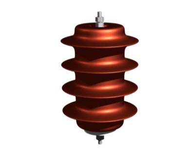
A Sheath Voltage Limiter (SVL) is a protective device used to limit transient overvoltages in the cable sheath. It is mainly installed at points where the sheath is left floating, such as in single-end bonding, mid-point bonding, and cross bonding systems. Under normal conditions, the SVL remains inactive. But during faults or transient surges, it provides a low-resistance path for the excess voltage to safely discharge to the ground.
Why is SVL Needed?
When a cable is single-end bonded, the sheath is grounded only at one end, and the other end remains floating. This can lead to high induced voltage at the open end. Similarly, in cross bonding, different sections of the sheath are left ungrounded, causing potential build-up. If this voltage is too high mainly during a fault, it may exceed the insulation strength and damage the sheath. SVLs prevent this high voltage event by limiting the voltage within a safe range.
How Does an SVL Work?
SVLs work like surge arresters. Basically a sheath voltage limiter is a lightning arrester. Under normal conditions, they act as an insulator, blocking any current flow. But when the voltage at the sheath crosses a certain threshold, the SVL turns conductive, diverting the excess energy safely to the ground. Once the transient is over, it returns to its insulating state.
Where Are SVLs Installed?
- At the open end of a single-end bonded cable.
- At sectional joints in a cross-bonded system.
- At the mid-point grounding location in mid-point bonding.
- Near high-voltage substations where transient surges are common.
Advantages of Using SVL
- Protects the sheath insulation from overvoltage damage.
- Prevents unsafe voltage build-up at ungrounded points.
- Ensures the long-term reliability of the cable system.
- Works automatically without the need for external controls.
However, proper selection and installation of SVLs are important. The rated voltage of the SVL should match the expected induced voltage in the sheath. If the wrong rating is used, it may not function correctly, leading to insulation stress or unnecessary tripping.
In conclusion, Sheath Voltage Limiters (SVLs) are essential in high-voltage cable systems where sheath bonding methods leave certain points ungrounded. Without them, the sheath can be exposed to dangerous voltage levels, increasing the risk of failure. By using SVLs at the right locations, the system remains safe, reliable, and efficient.
How to Select Sheath Voltage Limiters?
As I have already told, Sheath Voltage Limiters (SVLs) are used in high-voltage cable systems to protect the cable sheath from overvoltage. But selecting the correct voltage rating of an SVL is very important. If the rating is too low, the SVL may operate unnecessarily. If it is too high, it may not provide protection when needed. So, the SVL must be chosen carefully based on the system requirements.
The first step is to determine the maximum induced voltage(E) on the cable sheath under normal and fault conditions. This voltage depends on:
The length(L) of the cable – longer cables have higher induced voltage.
The current(I) flowing through the conductor – higher current leads to higher induced voltage. This current is taken from the fault level of the system.
Another parameter(k) provided by cable manufacturer is induced voltage per km for 1 kA of current through the main conductor.
The induced voltage is calculated using the formula: \[ E = k \times L \times I \]