In electrical power systems, circuit breakers play a crucial role in protecting equipment and ensuring the stability of the grid. However, improper operation of breakers can lead to major fault and unsafe conditions. One critical issue in breaker operation is multiple closing attempts before clearing a fault. This can occur due to a continuous closing signal to the closing coil. To prevent this situation the anti pumping scheme comes into play. The anti-pumping mechanism ensures that the breaker closes only once per closing command, even a continuous closing command passes from the remote or local closing switch. Let us break down how this scheme works, using the provided control circuit diagram as an example.
Anti Pumping Circuit Diagram
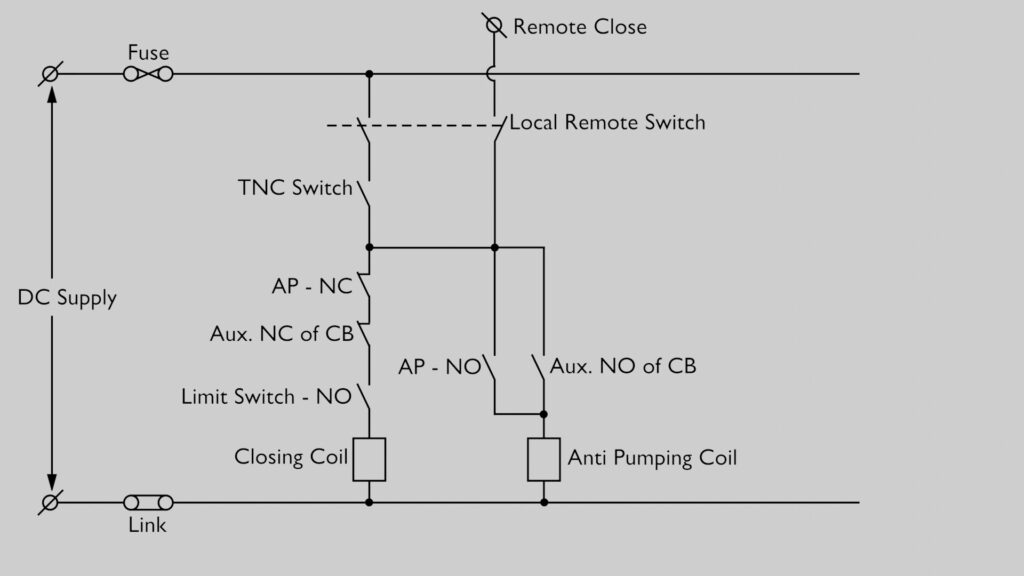
The diagram represents a part of a DC control circuit designed for closing a circuit breaker while incorporating an anti-pumping relay to prevent unintended repeated operations.
Here, the DC Supply provides the required power for control operations. The Remote Close terminal sends a closing pulse from the remote control panel. This remote close signal is generated by a TNC switch or a Closing Push Button attached to the remote control panel.
The Local Remote Switch is used to select either local or remote operation. When the Local Remote Switch is in the Remote position, the closing control path is connected to the Remote Close circuit. Conversely, when this switch is in the Local position, the closing control path is connected to the positive DC supply bus of the circuit breaker.
The TNC Switch (Trip-Neutral-Close Switch) is a manually operated switch used for locally closing the breaker.
An Auxiliary Switch is fitted with the mechanism of the circuit breaker. When the CB closes, all the parallel NO (Normally Open) contacts close, and all parallel NC (Normally Closed) contacts open. Conversely, when the CB opens, all the parallel NO contacts open, and all parallel NC contacts close.
One of these NC (Normally Closed) contacts, which is connected in the closing circuit path, ensures that the breaker is open before attempting a closing action. That means this Auxiliary NC contact of the CB in the closing path ensures that the breaker can only close when it is open.
The Limit Switch (NO – Normally Open) ensures that the breaker is in the correct mechanical position before closing. The Limit Switch NO contact will close only if the Closing Spring is fully charged.
The Anti-Pumping Relay (AP) is connected in parallel with the closing circuit. There is an Auxiliary NO Contact in series with the Anti-Pumping Coil. An AP-NO (Normally Open) contact of the Anti-Pumping Relay itself is placed in parallel with that Auxiliary NO Contact.
From the above circuit, it is clear that the Anti-Pumping Coil is energized only via the series Auxiliary NO Contact during CB closing operations. Additionally, there is an AP-NC (Normally Closed) contact of the Anti-Pumping Relay in the closing circuit path, which initially allows the closing command to reach the Closing Coil.
How the Anti-Pumping Circuit Works
If we observe carefully, we will see all the contacts provided in the closing circuit remain closed when CB is open and spring is fully charged. So, when the Remote Close switch or Local TNC switch is pressed or operated, current flows through the circuit to energize the Closing Coil. This causes the breaker to close, and all the auxiliary NO contacts of the breaker switch to a closed state. As a result, the AP relay activates via its series Auxiliary NO contact and opens its AP-NC contact of the closing path, cutting off power to the Closing Coil and blocking further closing attempts. If the closing command is held continuously or issued multiple times in quick succession, the Anti-Pumping Relay (AP) prevents repeated operation. Once the Anti-Pumping Coil is energized, the AP-NO contact in series with Anti-Pumping Coil gets closed. This latchs the Anti-Pumping circuit untill the Remote Close switch or Local TNC switch is released.
Importance of the Anti-Pumping Scheme
Without an anti-pumping mechanism, continuous closing signals could cause the closing coil to overheat, leading to damage. Additionally, uncontrolled multiple closing attempts during fault could create instability in the power system and increase the risk of breaker failure during critical operations. By implementing an anti-pumping relay, the circuit ensures:
Conclusion
The anti-pumping scheme is a simple yet vital protection feature in circuit breaker control circuits. By ensuring that the breaker closes only once per command, it prevents unwanted repeated operations, reducing the risk of damage and improving system reliability. This mechanism is essential in all modern high-voltage circuit breaker designs and plays a key role in maintaining stable and efficient power system operations.