What are the short circuit withstand levels for 400kV, 220kV, and 132kV transformers?
400 kV transformers must withstand 63 kA for 1 second.
220 kV transformers must withstand 50 kA for 1 second and 40 kA for 3 seconds.
132 kV transformers must withstand 40 kA for 1 second and 31.5 kA for 3 seconds.
66 kV transformers must withstand 31.5 kA for 3 seconds.
33 kV transformers must withstand 25 kA for 3 seconds.
What is the purpose of tertiary winding in a 220/132/33 kV transformer?
A 220/132/33 kV transformer has a delta-connected (Δ) tertiary winding of 33 kV voltage level. Delta-connected tertiary windings help in reducing third harmonics. It provides a closed path for third harmonic currents and prevents them from affecting the primary and secondary systems. Additionally, it may supply local 33 kV loads.
What is the MVA rating of the tertiary winding in a 315 MVA, 400/220/33 kV transformer?
The MVA rating of the tertiary winding in a 315 MVA, 400/220/33 kV transformer, as per the WBSETCL specification, is 5 MVA.
How does the tertiary winding help in harmonic suppression and stability?
In three-phase transformers, third-harmonic currents (3rd, 9th, 15th, etc.) naturally occur due to the nonlinearity of magnetizing currents. If a delta-connected tertiary winding is present, it provides a closed-loop path for these harmonic currents. The harmonics circulate within the delta winding rather than flowing into the power system, preventing voltage distortion in the primary and secondary windings. So, it reduces harmonic content in the main windings (HV and LV). In Y-Y connected transformers, third harmonics can cause neutral displacement (floating neutral effect). Hence, a tertiary winding prevents the neutral shifting.
What are the short-circuit withstand conditions for a transformer?
The transformer must withstand the thermal effects of a short circuit. The magnitude of current and the time duration for short-circuit withstand are the main factors of withstand capability. The maximum permissible winding temperature after a short circuit must not exceed 250°C. We must also consider the mechanical as well as thermal ability to withstand a short circuit.
What is the purpose of the Dynamic Short Circuit Test, and how is it performed?
The Dynamic Short Circuit Test evaluates a power transformer’s ability to withstand mechanical and thermal stresses from high fault currents. During a short circuit, strong electromagnetic forces act on the windings, risking mechanical deformation, insulation damage, or structural failure. This test ensures the transformer remains operational under real-world fault conditions.
As per IS 2026 (Part-5) / IEC 60076-5, we conduct the test in a high-power laboratory. Here, we short-circuit the LV winding. We apply the fault for 0.1 to 0.5 seconds per cycle at HV. Then, we repeat 3 to 6 times with cooling intervals. Here, we closely monitor the winding displacement, mechanical oscillations, and insulation integrity.
Then we analyze the post-test, SFRA, winding resistance, and leakage reactance. A transformer passes if no mechanical deformation occurs, insulation remains intact, and leakage reactance deviation is ≤2%. This test is mandatory for 400 kV, 220 kV, and 132 kV transformers to ensure reliability in power networks.
How is the Lightning Impulse Test performed on a 220/132 kV transformer?
The test ensures the transformer can handle sudden voltage spikes due to natural lightning without insulation failure. The test follows IS 2026 (Part-3) / IEC 60076-3 standards. Here only the winding under test remains open. We connect all other terminals to ground. A high-voltage impulse generator applies controlled surges. An oscilloscope records the response.
We apply a standard lightning impulse wave (1.2/50 µs) three times. This represents a real lightning strike. Next, two chopped wave impulses (1.2/3-5 µs) simulate system switching disturbances.
The oscilloscope records waveforms for analysis. Here, we check the voltage distortion and neutral displacement. The transformer passes the test if there is no waveform distortion.
What is the purpose of the Sweep Frequency Response Analysis (SFRA) Test?
The SFRA test checks the mechanical and electrical condition of a transformer. It helps find winding displacement, core movement, and insulation failures. Regular electrical tests cannot detect these faults. The SFRA test is useful after short circuits, transportation, or heavy faults to ensure the transformer is safe to use.
We apply a low-voltage AC signal to the winding. The voltage is ≤10V AC (RMS), and the frequency ranges from 20 Hz to 2 MHz. We measure the transformer’s response and compare it with a reference signature. Any change in response from past reference shows possible internal damage.
We perform the test in two configurations. In the open circuit mode, we excite one winding with the SFRA signal by keeping the other windings open. This helps check the core and insulation condition.
In the short circuit mode, we short one end of the winding with all other terminals and ground together, and the SFRA signal is applied to the opposite end. This helps detect winding deformation, shorted turns, and mechanical stress.
The SFRA test is a non-destructive method to find faults before they cause failure.
What is the applied voltage range for SFRA testing?
The applied voltage range for Sweep Frequency Response Analysis (SFRA) testing is typically ≤10V AC (RMS).
- Minimum Voltage: 0.5V AC
- Maximum Voltage: 10V AC (RMS)
- Frequency Range: 20 Hz to 2 MHz
We keep the voltage low to prevent core saturation and avoid stressing the insulation. The goal of the test is to measure the frequency response of the transformer windings without affecting its normal parameters.
What are the different transformer oil tests, and why are they important?
We test transformer oil as per IS 335. The following tests are specified for new insulating oil in transformers:
Breakdown Voltage (BDV) Test
Purpose: Measures the dielectric strength of the oil.
Requirement: Minimum 60 kV (RMS) after treatment. The same should be at least 30 kV before filtration.
Importance: Ensures the oil can withstand high electrical stress without breakdown.
Moisture Content Test
Purpose: Detects water contamination, which affects insulation strength.
Requirement: Below 72.5 kV: < 25 ppm
72.5 kV to 145 kV: < 20 ppm
Above 145 kV: < 15 ppm
For old oil it must be less than 50 ppm.
Importance: Prevents insulation failure due to moisture absorption.
Resistivity Test
Purpose: Measures the ability of oil to resist electrical conduction.
Requirement: 35 × 10¹² Ω-cm at 90°C and 1500 × 10¹² Ω-cm at 27°C.
Importance: Higher resistivity at both higher and normal temperatures ensures better insulation properties for the normal to maximum temperature limit.
Dielectric Dissipation Factor (Tan Delta) Test
Purpose: Evaluates energy loss in insulation due to impurities.
Requirement: Max 0.002 at 90°C.
Importance: Ensures minimal loss and higher efficiency.
Interfacial Tension (IFT) Test
Purpose: Measures surface tension between oil and water.
Requirement: ≥ 0.04 N/m at 27°C.
Importance: A lower IFT indicates oil degradation and contamination.
Flash Point Test
Purpose: Determines the minimum temperature at which oil vapors ignite.
Requirement: ≥ 140°C.
Importance: Ensures the fire safety of the transformer.
Acidity (Neutralization Value) Test
Purpose: Measures acidic content, which can corrode transformer parts.
Requirement: Max 0.03 mg KOH/g
Importance: Prevents insulation deterioration due to acidic degradation.
How is the temperature rise test conducted, and what are the permissible limits for winding and oil?
Temperature Rise Test Procedure
Test Prerequisites
The transformer must be fully assembled, including its cooling system. Specifically, we have fitted radiators, fans, and oil pumps. Additionally, we fill the transformer with insulating oil. Finally, we measure the ambient temperature and record it.
Loading the Transformer
Here, we stimulate the load to the transformer. Since applying the full rated load directly might be impractical, the test is often conducted using the short-circuit method. In this approach, the secondary winding is shorted, and a reduced voltage is applied to the primary winding to circulate the rated current through the transformer. Consequently, this simulates full-load losses (copper losses) without requiring a full load on the secondary side.
Duration of the Test
The transformer is operated at rated current until thermal equilibrium is reached. Here, equilibrium means when the temperature stops rising significantly—typically within 1°C over a specified period, such as 1 hour or 30 minutes. Generally, this may take several hours to reach equilibrium, depending on the transformer size and cooling system.
Oil Temperature Measurements
Oil temperature is measured using thermometers or thermocouples placed in the top oil. Additionally, the bottom oil temperature is also sometimes measured to calculate the temperature gradient.
Winding Temperature Measurements
Direct measurement of winding temperature is challenging during operation; therefore, it is calculated indirectly. Following equilibrium, the test current is switched off, and the winding resistance is measured immediately and over time as it cools. Subsequently, the resistance change from its initial value before the start of the temperature rise test is used to calculate the average winding temperature rise.
For this calculation, we use the standard formula:
\[ \theta_w = \frac{(R_2 – R_1)}{R_1} \times (235 + t_1) \]
Where:
- \(\theta_w\) = Winding temperature rise
- \(R_1\) = Winding resistance at initial temperature \(t_1\) (before test). Notably, it is normally considered as ambient temperature, as it is very close to ambient temperature
- \(R_2\) = Winding resistance after test
- 235 = Constant for copper windings (alternatively, for aluminum windings, use 225)
What types of bushings are used in power transformers?
There are many types of bushings used in high-voltage power transformers. These are Resin Impregnated Paper (RIP) Bushings, Oil Impregnated Paper (OIP) Bushings, Porcelain Bushings, and Polymer/Composite Insulator Bushings.
What are the insulation resistance requirements for a transformer core?
The insulation resistance of the core-clamp link must be more than 1 Giga-ohm.
What is the Nitrogen Injection Fire Prevention System (NIFPS), and how does it work?
The Nitrogen Injection Fire Protection System (NIFPS) is designed to prevent and extinguish fires in oil-filled transformers by employing a coordinated sequence of actions based on a “drain and stir” principle. Upon detecting internal faults or external fires through protective relays and heat detectors, the system activates and initiates the following steps:
Oil Draining: A quick-opening drain valve releases a predetermined volume of hot oil from the upper section of the transformer. This process reduces internal pressure and removes overheated oil that could fuel combustion.
Conservator Isolation: The Transformer Conservator Isolation Valve (TCIV) closes to prevent oil flow from the conservator tank to the main tank, thereby limiting the amount of oil available that could sustain a fire. The shutting of the TCIV accelerates the lowering of the oil level in the tank.
Nitrogen Injection: Nitrogen gas is injected under pressure into the bottom of the transformer tank. As the nitrogen rises, it stirs and cools the remaining oil, lowering its temperature below ignition levels. Additionally, the nitrogen occupies the space created by the drained oil, forming an insulating layer that separates the oil from oxygen, thus preventing combustion.
This integrated approach ensures rapid suppression of fires, typically within 30 seconds.
How Does a Tertiary Winding Suppress Unbalanced Load in a Three-Phase Transformer?
Normally, in a balanced system, the vector sum of the three-phase fluxes is zero. Suppose the secondary winding of a three-phase system experiences an unbalanced load. That means one phase has a higher current than the others. The flux produced in the core by each phase winding becomes unequal. Thus, under unbalanced conditions, the sum is no more zero. This leads to a residual or zero-sequence flux in the core. This zero sequence flux distorts the magnetic balance in the core. This magnetically unbalanced core creates unbalanced voltage in a three-phase system.
A delta-connected tertiary winding provides a closed-loop path. The residual flux caused by an unbalanced load induces a circulating current in that closed delta winding. This circulating current generates a compensating magnetic flux that opposes and cancels out the residual or zero sequence flux in the core. As a result, the net residual flux in the core is minimized, stabilizing the transformer voltage. Therefore, the tertiary winding reduces voltage fluctuations in the main windings, keeping phase voltages closer to their ideal values.
The tertiary winding also helps in circulating third-harmonic components in the same manner. So, it also prevents third-harmonic components from propagating into the power system.
How does an On-Load Tap Changer (OLTC) function?
On-Load Tap Changer (OLTC)
Need for Tap Changers
In an electrical system, load fluctuations lead to voltage variations. Therefore, to maintain supply voltage within specified limits, a power transformer requires a tap changer. Generally, there can be two types of tap changers: off-load tap changers and on-load tap changers. In this discussion, we will focus on the functional process of on-load tap changers or OLTCs. Notably, these tap changers shift between adjacent tap positions while the transformer remains loaded. As a result, these allow voltage adjustment without interrupting the power supply.
Switching Circuit of OLTC
The diagram represents a typical circuit arrangement for an OLTC in a single-phase winding. However, for a 3-phase transformer, the same arrangement is provided for each phase winding.
Components of OLTC
The setup consists of moving contacts (a and b) and contactors (C-1 and C-2). Additionally, there is a reactor between C-1 and C-2, as shown. Furthermore, the reactor has a central tap connected to one-half of the transformer winding.
Normal Operating Condition
Under normal conditions, both moving contacts a and b remain connected to fixed tap-changer contacts, and both contactors (C-1 and C-2) remain closed. Consequently, this allows load current to flow through them as well as both halves of the reactor coil.
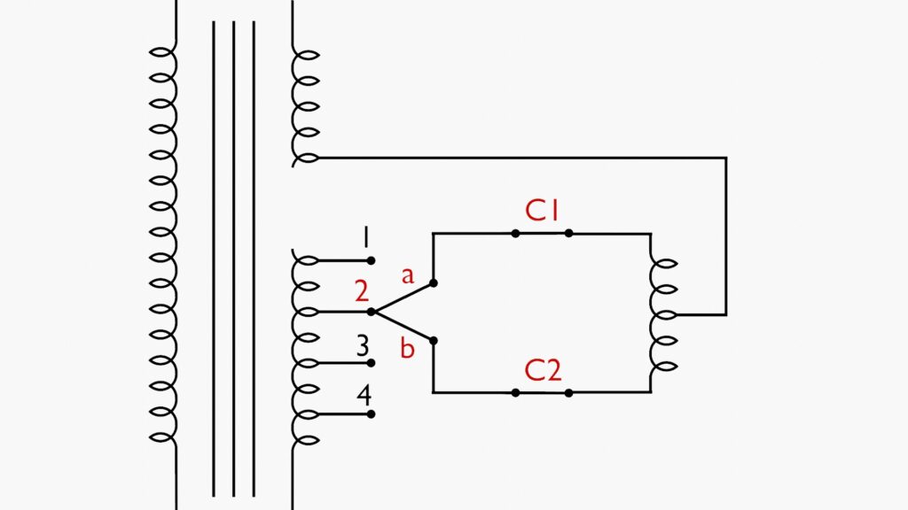
During a tap change, for example, from tap position 2 to tap position 3, the process occurs in a stepwise manner

Opening Contact C-2: Initially, C-2 is opened, and moving contact ‘b’ is switched to the fixed contact of tap 3.
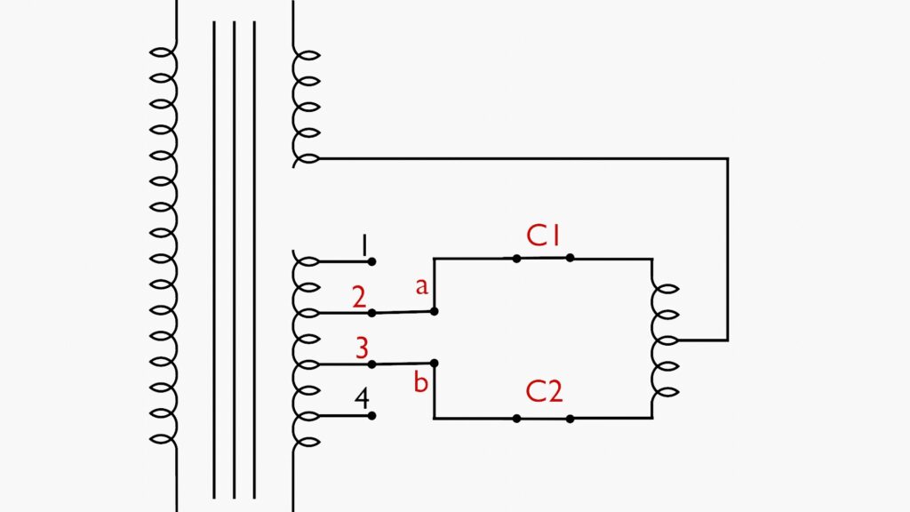
Closing Contact C-2: Once b is in position, C-2 is closed, which shorts the winding section between taps 2 and 3 across the reactor R. The reactor helps control the circulating current that arises due to the voltage difference between the two tap positions.

Opening Contact C-1: After C-2 is secured, C-1 is opened, and moving contact a is switched to fixed contact 3.

Closing Contact C-1: Finally, C-1 is reclosed, completing the transition from tap position 2 to 3.
The reactor between C-1 and C-2 is carefully selected to provide adequate reactance. This helps ensure that the circulating current remains at a minimal level.
What is the tap range normally followed in an on-load tap changer?
The range normally followed in an on-load tap changer is 1.25% voltage variation per step in 16 equal steps. That means the tapping range is ±10% of the nominal voltage.
Why is an oil pot provided in the breather of a transformer?
The oil pot at the bottom of the breather prevents direct atmospheric moisture from entering the silica gel. The incoming air must pass through a small layer of oil, which traps moisture and dust particles. It creates a barrier between the silica gel and the outside air.
What are the recommended temperature settings of the cooling controller of a power transformer?
Based on standard practices, the typical temperature settings for cooling system operation in power transformers are:
- Cooling Fans (ON/OFF settings):
- ON at: 70°C (Oil Temperature)
- OFF at: 65°C (Oil Temperature)
- Oil Pump for Forced Oil Cooling (ON/OFF settings):
- ON at: 75°C (Oil Temperature)
- OFF at: 70°C (Oil Temperature)
- Alarm Settings:
- Oil Temperature Alarm: 85°C
- Winding Temperature Alarm: 90°C
- Trip Settings:
- Winding Temperature Trip: 95°C
Why is the winding conductor transposed at different intervals in a power transformer?
Normally, there are two or more insulated copper strips running in parallel to form a conductor of winding. This is done to reduce the skin effect of the conductors. As the insulated strips or strands are placed parallel in a winding, the magnetic flux linkage from the core may slightly differ from one strip to another. This variation of flux linkage induces slightly different voltages on the strands. These voltage differences cause circulating currents to flow between them. This phenomenon leads to losses and localized heating due to circulating current. Transposition of strands or strips in a winding ensures uniform flux linkage with all strips in a winding. That means the average magnetic flux linkage for each conductor becomes nearly identical, balancing the current flow. As a result, it results in an even flow of current through each conductor of the winding.
In simple words, it can be said that, for a uniform magnetic flux linkage from the core to each conductor of a winding, the conductors are transposed at sufficient intervals along their length.
Video on the Working of a Transformer
How is the system earthing arranged for HV and tertiary windings of power transformers?
Tertiary winding–equipped transformers are normally auto-transformers. The high-voltage side of the transformer is connected in star. This star point is solidly grounded (dead earthed). Therefore, the neutral is directly connected to earth without any impedance.
The tertiary winding remains in a floating condition. It does not have any direct connection to the earth.
What percentage loading corresponds to ONAN, ONAF, and OFAF ratings?
For the ONAN cooling method, 60% loading is permitted. The ONAF cooling method corresponds to 80% loading, and the OFAF cooling method corresponds to 100% and above ratings of the transformer.
What are the maximum top oil temperature rise and winding temperature rise limits?
The maximum oil temperature rise is limited to 50°C above ambient temperature. The maximum winding temperature rise is limited to 55°C above ambient temperature. During a short-circuit condition of 3 seconds, the maximum permissible average winding temperature may reach 250°C.
What is the accuracy class of WTI (Winding Temperature Indicator)?
± 1.5% or better
What short-circuit withstand currents are generally specified for 400 kV, 220 kV, 132 kV, 66 kV, and 33 kV systems?
The short-time withstand current ratings are as follows:
- 400 kV system – 63 kA for 1 second
- 220 kV system – 40 kA for 3 seconds
- 132 kV system – 31.5 kA for 3 seconds
- 66 kV system – 31.5 kA for 3 seconds
- 33 kV system – 25 kA for 3 seconds
These values represent the maximum short-circuit current that the system equipment can safely withstand for the specified duration without thermal or mechanical damage.
What is the OLTC range in power transformers of more than 20 MVA?
For power transformers above 20 MVA, the voltage tapping range is controlled through the On-Load Tap Changer (LTC). The voltage variation provided by the LTC ranges from −10% to +10% of the rated voltage. The transformer has a total of 17 tap positions, including the normal tap position at position 9.
Tap positions 1 to 8 represent the lower voltage range. Position 9 is the normal voltage position. Tap positions 10 to 17 represent the higher voltage range above the normal voltage. There are 8 tap steps on each side of the normal tap position. Therefore, the total voltage variation of 20% is divided into 16 steps. Hence, the voltage change per tap position is 1.25%.
What standard governs transformer oil quality?
IS – 335
What is the minimum interfacial tension at 27°C?
0.04 N/m at 27°C
What breakdown voltage is required after treatment?
60KV
What resistivity values are specified at 90°C and 27°C?
35X1012 Ohm – cm and 1500X1012 Ohm – cm
What is the maximum tan delta at 90°C?
0.002 at 90°C
What are the permissible moisture contents before commissioning?
15 ppm
What is IP protection?
Let us explain IP protection. IP stands for Ingress Protection. There are two types of ingress: one is solid particles (dust), and the other is liquid (water). Based on protection against these two types of ingress, IP ratings are defined for electrical cabinets and equipment.
The IP rating is written as IPXY, where X and Y are digits.
- X indicates protection against solid ingress.
- Y indicates protection against liquid ingress, meaning water.
If X = 5, it means dust is protected. A small quantity of dust may enter, but it will not affect operations.
If X = 6, it means dust-tight. No dust can enter the cabinet.
For liquid ingress, common levels are 5, and 7:
- Y = 5 means protection against water jets, such as rain or water sprayed from any direction.
- Y = 7 means the cabinet can be temporarily immersed in water without water entering inside.
Therefore:
- IP55 means dust protected and protected against water jets from all directions.
- IP65 means dust-tight and protected against water jets.
- IP67 means dust-tight and protected against temporary water immersion (water-tight).