Sweep Frequency Response Analysis (SFRA) is a powerful diagnostic tool. We use it to detect only mechanical issues inside a transformer. It helps identify winding movement, core displacement, insulation failure, and structural deformations. SFRA shows how the transformer responds to different frequencies.
Working Principle of SFRA
In SFRA, the analyzer kit injects a low-voltage AC signal into a transformer winding. The frequency of the input AC signal varies typically from 20Hz to 2MHz. The analyzer measures the output voltage simultaneously. Also, the analyzer plots the result as a frequency response curve. The frequency response curve acts as a fingerprint for the transformer. Actually, SFRA considers the transformer as an RLC circuit.
Each transformer has a unique frequency response signature. We record this signature when the transformer is healthy. Later, we perform an SFRA test again. We compare the new response curve with the previous reference curve. If the curves differ significantly, it indicates internal deformation or insulation deterioration.
Why SFRA is Important
If the transformer experiences mechanical stress during transportation, internal parts may shift. Aging can also weaken the insulation system. High short-circuit currents can deform windings or displace core structures. When any internal part moves or deforms, the transformer’s electrical parameters change. The effective resistance (R), inductance (L), and capacitance (C) values change. As a result, the equivalent RLC network of the transformer changes. Because of this change, the frequency response curve also changes.
Types of SFRA Tests and Connection Methods
We use different SFRA tests to assess different parts of a transformer. There are normally three leads in an SFRA kit. One lead, normally of yellow color. It injects a sinusoidal low-voltage signal. The second lead is red, and we use it to measure the injection voltage. The third lead is the blue lead. We use it to measure the output or response voltage signal.
Open Circuit SFRA Test
The open Circuit SFRA test checks the core and insulation conditions. Here, we connect the yellow (voltage source lead) and the red (input measuring lead) leads together at one terminal of the winding. Then we connect the blue (output) lead to the other terminal of the winding. All other windings remain open.
Short Circuit SFRA Test
The short circuit SFRA test detects displacement, deformation, and defects of windings. Here, we connect the yellow and red leads to one terminal of the winding under test. Blue lead goes to the other terminal. The secondary winding is short-circuited to eliminate the core’s influence.
How to Interpret SFRA Results
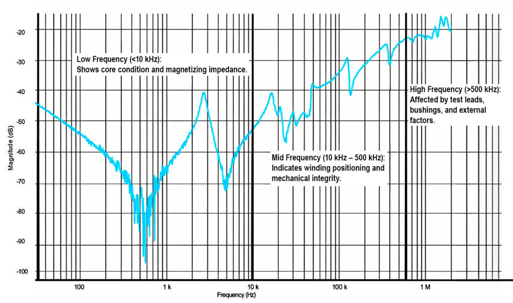
The SFRA trace consists of three key frequency regions, each revealing different transformer characteristics:
Low Frequency (<10 kHz): Shows core condition and magnetizing impedance.
Mid Frequency (10 kHz – 500 kHz): Indicates winding positioning and mechanical integrity.
High Frequency (>500 kHz): Affected by test leads, bushings, and external factors.