Before entering the topic of line differential protection, or simply differential protection of a transmission line, we shall first recall our concept of differential protection. Actually, the differential protection used for a transmission line is called line differential protection. We have already heard about the differential protection of transformers, busbars, etc. The same principle is applied to a transmission line, and hence the protection scheme is termed line differential protection.
Today, the power network has become quite complex. There are a large number of interconnected transmission lines and substations. The delay tripping or non-tripping of any part of the network during a real fault may cause serious damage to the other part of the network. Therefore, it becomes the priority nowadays to isolate the faulty part of the network without any time delay. Also, in addition to that, the isolated part of the network must be the faulty one only. Otherwise, there may be problems raised in the healthy part of the network. This is why the modern protection system demands high selectivity. The time differential protection scheme also provides that. So, it is a high-speed, selective protection system. This is an example of a unit protection system.
In brief, we can say, power line differential protection offers very fast isolation of the faulty portion of the network – often within 15 to 20 milliseconds. This rapid isolation prevents cascading failures, which can escalate into a large-scale blackout.
Working Principle of Differential Protection
The working principle of differential protection depends on Kirchhoff’s Current Law. This law says that the vector sum of all the currents entering and leaving a node is zero. In a differential relay, there is a path through which the differential current passes. What is the differential current? A differential current is the resultant of the vector sum of all the currents entering and leaving a node. Suppose there is a black box that represents electrical equipment to be protected by a differential protection scheme. Now, current \(I_1\) is entering the black box, and current \(I_2\) is leaving the black box. Finally, the sum of these two currents is \(I_1+I_2=0\).
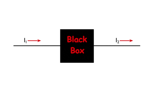
Because if we consider \(I_1\) as positive, then \(I_2\) is negative. This is because one is entering and the other is leaving. Now suppose these two currents differ, either in magnitude or in phase, or in both magnitude and phase. At that time, the sum of \(I_1\) and \(I_2\) is no longer zero. That means \(I_1+I_2≠0\).
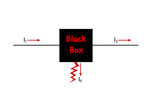
That situation can only happen when there is a diversion path in the black box through which some portion of the input current is diverted elsewhere. Then, the input and output terminal currents are no longer balanced. This diversion may occur only during a fault in the black box. If any fault occurs outside the black box, the overall current will increase, but at both the input and output sides. Therefore, the vector sum of the input and output currents still remains zero. Actually, the differential relay senses the unbalanced current and sends a trip signal to the circuit breakers on both sides of the black box. Therefore, the black box is isolated from the rest of the system instantly.
Working Principle of Line Differential Protection
In a long transmission line, a single differential relay cannot be used for this purpose. This is because the input point and output point, as we just discussed, are the sending end and receiving end of the transmission line. These two ends are far away from each other. One is in one substation, and the other is in a different substation.
Without discussing any further, let us directly enter into the actual scheme of line differential protection. That will help you understand the concept clearly.
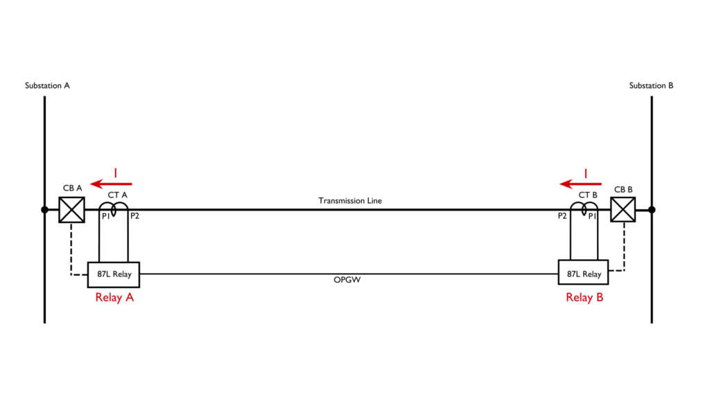
In the above image, you can see that there are two substation buses. One is in substation A, and the other is in substation B. Both of these buses are connected by a transmission line. 87L refers to the line differential relays. The 87L relay at substation A is named Relay A, and it is associated with the Line CT of the transmission line at substation A. The relay can initiate the tripping signal for the circuit breaker of the same line at substation A, and that CB is named as CB – A in the above diagram. A similar arrangement is made at substation B, as also shown in the above diagram.
Now, as the 87L relays at both ends are differential, they continuously compare the sending-end and receiving-end currents. If any mismatch is found, the relay will initiate the tripping of the associated circuit breaker.
So, there must be some means by which the primary current sensed at one end of the line is compared to the primary current sensed at the other end of the line. This comparison is done using OPGW, meaning Optical Ground Wire.
Suppose current I is flowing through the transmission line. CT A senses the current and sends it to Relay A.
CT B senses the current and sends it to Relay B. This analog replica is then converted into a digital replica in the relay. This is because the current signals propagate through OPGW in optical form, from one end relay to another end relay. Actually, in Relay A, the secondary current signal is first converted to its digital form, then, for propagation through OPGW, it is converted to its optical form, and at the other end, meaning at Relay B, it is reconverted to its digital form for comparison.
That means at Relay B, it is reconverted to its digital form. Here, Relay A compares the digital form of current from CT A and the current from CT B reaching via Relay B and OPGW. If any mismatch is found, Relay A will initiate tripping of circuit breaker CB A. Instantaneously, the same thing happens in Relay B, and it causes tripping of the associated circuit breaker CB B. This is the basic working principle of line differential protection.
The key components required for line differential protection are the current transformers, differential relays, and a communication channel like OPGW.
Suppose there is a fault occurring at Bus A of Substation A. The fault current will also be contributed by the connected transmission line. At that time, the CT current will increase, but it will increase in both CTs. So when Relay A compares current from CT A and CT B, it will not find any difference, i.e., no differential current. Similarly, as CT A and CT B currents are the same, Relay B will also not find any differential current; hence, CB B will not trip.
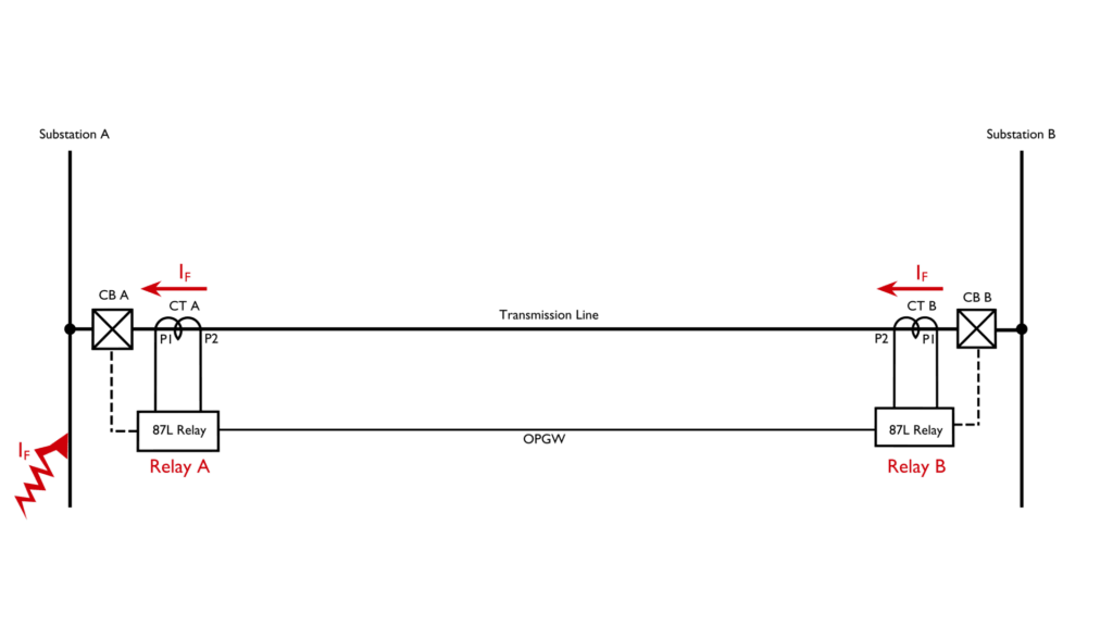
Here, you see, we have connected \(P_1\) primary terminals of both CTs towards its substation bus. So during a fault at Bus A, the contributed fault current shall enter through \(P_2\) and leave through \(P_1\). For the same fault, the fault current enters through \(P_1\) and leaves through \(P_2\) at CT B. Therefore, with respect to the CT polarity, the current through CT A becomes the opposite phasor of the current through CT B. Therefore, during comparison, both relays find that the sum of these two currents is zero.
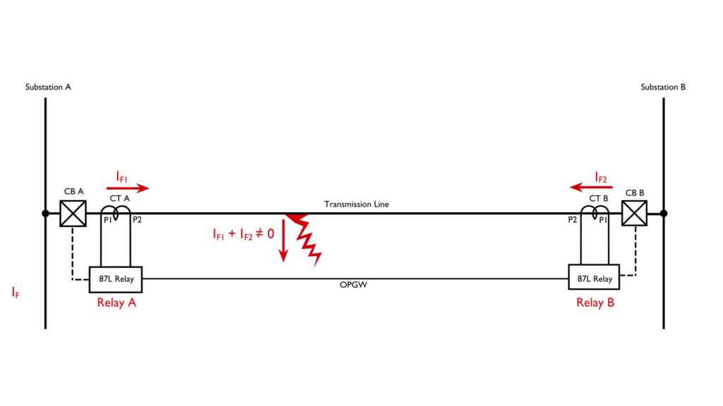
Now consider a fault occurring in the transmission line. The faulty point takes current from both Bus A and Bus B. At substation A, the fault current enters via \(P_1\) and leaves through \(P_2\). At substation B, the fault current enters via \(P_1\) and leaves through \(P_2\). Therefore, the phasors of both currents are not 180° apart, and also the magnitudes of both currents are different in this case because they are sourced from two different parts. In this case, Relay A and Relay B both will sense a differential current and operate the associated circuit breaker. Therefore, the entire transmission line is isolated instantly. The entire process takes only 15 to 20 milliseconds to complete.