The Earth Continuity Conductor or ECC provides an alternate fault current path in EHV installations, limiting dangerous sheath voltage and safeguarding cable insulation. Sometimes, we also call it Earth Continuity Cable.
We most commonly use single-core cables for underground high-voltage transmission systems. This is because 3-core high-voltage transmission cables, mainly above 33kV, are not easily transportable due to their very thick insulation and weight. A single-core cable is lighter than a three-phase or 3-core cable. A metallic sheath covers the insulation of these single-core cables. This metallic sheath acts as an electrical shield. We connect the metallic sheath of the cable to the ground at least at one point to fulfill its electrical shielding function.
Grounding the sheath confines the electric field produced by the high voltage conductors within the insulation. Therefore, it reduces the degradation of the insulation. Also, the metallic sheath provides a return path to the current during faults. Normally, we do not earth both ends of a metallic sheath. Although both-end bonding provides better shielding, it has many disadvantages.
Disadvantages of Both End Bonding
When we ground more than one point of a cable sheath, circulating currents flow continuously under normal loading, causing heating and derating. Due to this induced circulating current in the sheath, there will be a continuous ohmic loss in the cable, which makes the cable hot. Therefore, this causes a derating of the cable. Although “both-ends-bonding” reduces the voltage developed across the cable sheath due to induction. Although an induced current causes a derating of the cable.
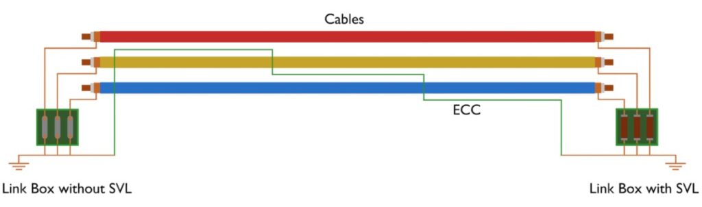
To overcome this disadvantage of both-end bonding, single-end bonding and cross-end bonding come into the picture. In single-end bonding, one end of the sheath is in a floating condition. The floating or open end of the cable sheath may suffer from dangerously high voltage even under normal loading conditions. For single-end bonding, the sheath voltage rises as the distance from the earthed end increases. We can mitigate the high induced voltage, especially during faults, by using sheath voltage limiters and installing an earth continuity conductor.
Here in this article, we shall discuss the basic theory of earth continuity conductor or cable (ECC).
Role of the Earth Continuity Cable or Conductor (ECC)
The earth continuity cable plays a vital role in both single-bonding and cross-bonding systems. This is essential to provide a return path to the fault current to the substation earthing system for the functioning of the protective relays. This acts just as the overhead GSS earth wire running through the tip of the towers.
Suppose we have not used any ECC in an underground cable. Then, in the event of a fault, the entire fault current returns through the sheath only. This may cause a significant rise in sheath voltage. On the other hand, if we have used ECC, the fault current gets an alternative path to flow towards the substation earthing grid. Therefore, the intensity of fault current in the sheath decreases, thereby reducing voltage rise beyond limits. So, we can consider it as a backup path for the fault current to return to the source earthing system.
Therefore, in short, we can conclude two main purposes of ECC:
- As this conductor provides an extra path for the fault current to return, the fault current through the sheath decreases. Hence, it reduces the probability of rising dangerously high sheath voltage during a fault. That means it limits the touch and step voltages.
- Like overhead GSS earth wire, it provides a return path to the fault current to reach the substation earthing system for an underground cabling system.
Key Aspects of an Earth Continuity Conductor
- The earth continuity cable must be of copper as per recommendations. This is because of its high conductivity and durability.
- Copper-clad steel is another alternative, which has higher mechanical strength. Although we most commonly use pure copper for this purpose.
- We normally use a very fine stranded conductor to increase the effective cross-section by reducing skin effects. Further, the finely stranded twisted conductor reduces the proximity effect. Hence, it increases further the effective cross-section. Twisting also increases the mechanical flexibility of the ECC.
- Insulation on an earth continuity conductor mainly provides a protective layer on the conductor.
- The cross-section of the conductor must ensure the short-circuit current rating of the system. Suppose, for a 220kV system, the sheath circuit current rating is 40kA for 3 seconds; therefore, the conductor (ECC) must be capable of withstanding that short-circuit current for that duration.