A Digital Teleprotection Coupler (DTPC) is often referred as a Digital Protection Coupler (DPC). It serves as a high-speed, reliable interface for transmitting protection commands between substations over a communication medium (OPGW). Typically it is used for carrier protection of transmission lines.
Working Principle
First, a protective relay such as a digital distance relay or a line differential relay detects a fault on the transmission line. The relay generates a digital signal if the relay is digital. Otherwise the relay will generate a contact-based signal (e.g., a logic high/low or relay contact closure). The DTPC receives the command from the relay via its input interface. If the signal is analog or contact-based, the DTPC or DPC converts it into a digital format using a microprocessor or digital signal processor. The microprocessor or digital signal processor also adds metadata, such as a timestamp, priority, or error-checking codes in the signal. Lastly, the result becomes a digitally encoded message suitable for transmission.
The encoded signal is transmitted over a communication channel. Nowadays, OPGW is used for the purpose. The full form of OPGW is Optical Ground Wire. It provides high-speed, noise-immune communication. The transmission of signal via OPGW is extremely fast, typically achieving latencies of 4-10 milliseconds, critical for real-time protection.
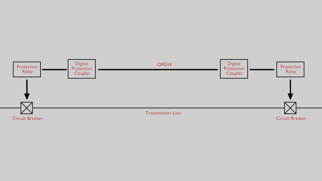
At the remote end, another DTC receives the transmitted signal. The DTC of the receiving end decodes the digital message, verifying its integrity using error-checking mechanisms. The DTC ensures the signal is valid and not corrupted. The decoded command is converted back into a format usable by the remote protective relay. If the relay is digital, it will be a digital signal. Else it will be converted back to the form of contact closure. The remote relay interprets the converted command. It trips the receiving end circuit breaker if a “trip” or “permissive” signal is received. It may inhibit the tripping if a “block” signal is received for an external fault.
Many DTCs include self-diagnostic features to monitor the health of the communication link and the device itself. This is done by loop testing with guard signal.
Guard Signal and Trip Signal
The guard signal is continuously sent by the Digital Protection Coupler (DPC) during normal operation. It works like a heartbeat to check if the communication link between two substations is active. This signal helps to detect link failures and prevents false tripping of the protection system. During normal operation, the guard signal is sent continuously to the remote end. This indicates that the link is healthy. As long as the receiving end detects this signal, it confirms that the communication channel is working properly.
When a fault occurs, the protective relay activates the DPC. This action stops the guard signal and sends a trip command instead. The receiving end detects the absence of the guard signal. It understands that a fault has been detected. This triggers the necessary protection action, such as tripping the circuit breaker.
If the guard signal suddenly stops without a trip command, it means there is a communication failure. The system then raises an alarm. This alarm notifies operators about a possible issue with the transmission channel. This helps them take corrective action quickly. An easy way to understand the guard signal is by comparing it to a heartbeat monitor in a hospital. When the heartbeat (guard signal) is steady, everything is fine. If it suddenly stops, there is a problem that needs immediate attention.
In digital teleprotection schemes, the guard signal is very important. It helps maintain a reliable communication link. It ensures that faults are detected quickly. It also prevents unnecessary tripping. This improves the stability and security of the power system.