Single Bus System with Bus Sectionalizer
Often, engineers adopt a single bus bar with a sectionalizing arrangement. Because it is cheap and simple. The figure just below shows a single bus bar with a sectionalizing arrangement. The scheme works best when the incoming and outgoing circuits are distributed evenly across the sections. When a single load requires double feeds, one circuit should come from one section and the other from the other section.
Suppose a single load needs a main supply and a standby supply. Here, the main supply comes from one section of the bus with a sectionalizer. The standby comes from the other section. In this arrangement, each section behaves as a separate bus. Any outage of one section does not affect the other section. The sectionalizer circuit breaker enables bus differential protection to trip only the faulty section. Therefore, it keeps the healthy section running.

This arrangement also serves a useful purpose when we use two transformers. Suppose the scheme includes two 33/11 kV, 6.3 MVA transformers. One transformer feeds the 11 kV supply to one side of the bus. The other transformer feeds the opposite section. There is an interlocking between the bus sectionalizer and the two incoming breakers. The interlocking is such that only two breakers can remain closed at a time. Normally, each section handles its own load. If we want to switch off one incoming circuit, we can close the sectionalizer breaker. This restores supply to the outgoing circuits of that section.
Double Bus System with Bus Coupler
Engineers widely use the double bus configuration in electrical power substations. It increases both reliability and operational flexibility. Engineers prefer it for medium to large substations. In most 220 kV AIS and GIS substations, engineers commonly apply this system. It includes two busbars that run parallel to each other. A bus coupler connects these two buses. Here, an operator can switch over a feeder from one bus to another without interrupting service. This feature ensures high reliability and flexible operation.

Operators normally distribute the incoming and outgoing feeders evenly between the two buses. In extreme conditions, they may connect all feeders to a single bus, especially during a complete bus shutdown. Therefore, the selection of bus rating must be such that it can carry all the feeders together simultaneously.
Key Components of a Double Bus System
- Two Buses: – The system has two separate buses. They run in parallel. Most diagrams label the buses as Bus 1 and Bus 2.
- Bus Coupler: A bus coupler switch interconnects the two busbars. It allows operators to transfer a feeder from one bus to another.
- Circuit Breakers: Each feeder line connects to each busbar through an isolator. The circuit breaker provides both protection and control.
- Isolators: Isolators isolate different sections of the system during maintenance.
- Current Transformers (CTs) and Potential Transformers (PTs): CTs and PTs measure current and voltage for relay protection.
Suppose operators need to shut down an entire bus, such as Bus-1. For that, they divert all feeders from Bus-1 to Bus-2. For that, an operator first closes the bus coupler isolators. Then the operator switches on the bus coupler breaker. Suppose a feeder connects to Bus-1. The operator needs to divert it to Bus-2 without any interruption. To achieve this, the operator closes the bus-side isolator of the feeder associated with Bus-2. Now the feeder becomes connected to both Bus-1 and Bus-2.
Next, the operator opens the bus-side isolator of Bus-1. In this way, the operator diverts all feeders one by one to Bus-2. Finally, the operator switches off the bus coupler breaker. Then the operator opens the bus coupler isolators. Now, Bus-1 is completely isolated from the live system. Finally, the operator can earth Bus-1 for maintenance.
Main and Transfer Bus System
The double bus system has no provision for circuit breaker maintenance without interruption of the feeder. This is the main disadvantage of a double bus system. Although it provides quite flexible and interruption-free bus maintenance. Although it does not provide any interruption-free individual circuit breaker maintenance. We can overcome this disadvantage with the main and transfer bus system. This system provides flexibility for carrying out breaker maintenance. Although it does not permit interruption-free bus maintenance. When a circuit breaker requires maintenance, operators shift the feeder to the transfer bus. Now, the feeder has become diverted through the transfer bus coupler breaker.
There is another disadvantage of the main and transfer bus system. It does not allow diversion of more than one feeder through the transfer bus at the same time.
One and Half Breaker Scheme of an EHV Electrical Substation
We also call the one and a half breaker scheme, as 1.5 breaker scheme. It is a common configuration of Ultra High Voltage (UHV) substations. Engineers normally use it for substations rated 400 kV and above. It is a compromise between the double bus double breaker (DBDB) scheme and the ring bus scheme. It offers high reliability, flexibility, and operational efficiency.

Key Features of the One-and-a-Half Breaker Scheme
For every two feeders, there are three circuit breakers. This results in 1.5 breakers per circuit, hence the name. The scheme typically uses two main buses (Bus A and Bus B). Breakers connect each circuit to both buses. Operators can power any circuit from either Bus A or Bus B. They can also carry out maintenance on any breaker or bus without interrupting the supply to the connected circuits.
The failure of one breaker does not affect the operation of the other circuits. On the other hand, if one bus fails or goes under shutdown, the other bus can take over the load. In spite of so many advantages, one and half bus system costs more than simpler schemes. This costs more than an equivalent-rated single bus or double bus single breaker (DBSB). Although it costs less than an equivalent-rated double bus double breaker (DBDB) scheme.
The middle breaker, also called the shared breaker, connects to both Bus A and Bus B. Among the other two breakers, one connects Bus A and the other connects to Bus B. Under normal conditions, both buses remain energized. The breakers then feed the circuits from the buses. If one bus fails, the other bus can supply power to all circuits. If a breaker fails, the adjacent breaker can take over its function.
Double Breaker Bus System
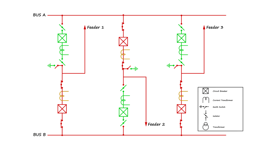
The double breaker bus system has two main buses. In the diagram above, the buses appear as Bus A and Bus B. Each feeder connects to either Bus A or Bus B through isolators and a circuit breaker. Every feeder has two circuit breakers: one directed toward Bus A and the other directed toward Bus B. One circuit breaker, along with its isolators, remains in the closed condition, while the other breaker and its isolators stay in the open condition.
Advantages of Double Breaker Bus Bar Systems
- Flexible Maintenance: In the diagram, the red section indicates live components. In contrast the green section indicates dead or isolated parts. We can easily take the green-side circuit breakers and current transformers into maintenance. During this period, the feeders remain active through the closed breakers on the red side. This ensures an uninterrupted supply even during the maintenance of circuit breakers and associated current transformers.
- No Interruption During Bus Maintenance: There is another key advantage of the double breaker bus system. It allows maintenance of any one of the buses without interrupting the supply lines. If one bus requires a shutdown, we can transfer all feeders easily to the other bus without any disruption.
- No Need for a Bus Coupler: Here, we can perform the transfer operation by switching only circuit breakers. So, this system requires no separate bus coupler arrangement.
Example of Operation of Double Breaker Bus
As shown in the diagram, Feeder-3 connects to Bus B. Suppose operators need to shut down the Bus B-side circuit breaker, which is currently ON. First, they close the isolators. Then they close the Bus A-side circuit breaker for Feeder-3. At this point, both buses supply the feeder.
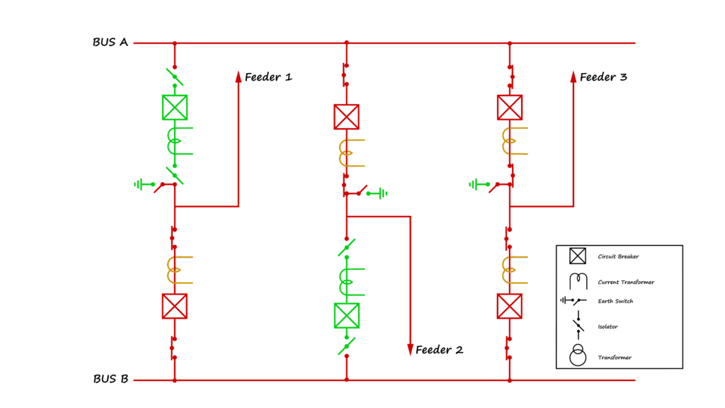
First, operators open the Bus B-side circuit breaker and then the associated isolators. This action transfers the feeder completely to Bus A. They can now safely take the Bus B-side breaker for maintenance.

This method allows a smooth transfer of a feeder from one bus to another without any interruption. It enables safe and uninterrupted maintenance activities without requiring a shutdown of the system.
Disadvantages of Double Breaker Bus System
- Higher Bus Rating Required: Operators must ensure that all feeders can divert to a single bus when required. During the shutdown of one bus, the other must have the capacity to carry the entire load. So, this increases the cost because of the high-rated buses.
- Increased Equipment Costs: Each feeder requires two circuit breakers. Hence, it increases overall expenditure. This configuration requires a greater number of isolators. Additionally, this adds cost further.
- Larger Space Requirement: Both AIS (Air-Insulated Switchgear) and GIS (Gas-Insulated Switchgear) installations require more space in a double breaker busbar system compared to a double bus single breaker system.